Build a TTQ in 5 "easy" steps ;-)
1) Check all the stuff
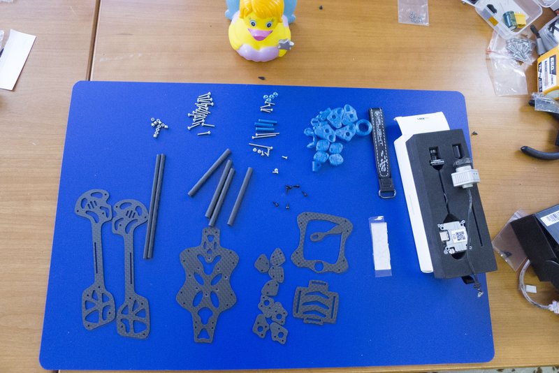
Make sure the framekit contains all the small pieces wich should at least include:
M2 Hardware:
|
TPU Parts:
|
Carbon:
|
You also should bring along:
|
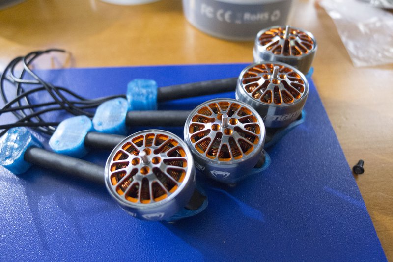
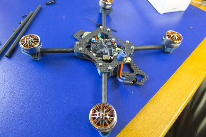
2) Arms & Motors (the hard Part)
I consider the assembly of the arms the (mechanically) hardest part of the built because the TPU requires a lot of pre-tension to provide enough grip on the carbon tubes and still isolate as much of the motor/prop vibration as possible.
Start by holding the motor-wires with needle-nose pliers as close to the stator as possible and bend the wires down:
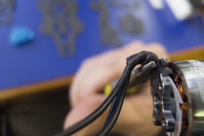
Do this slowly and be aware that you will most likely bend right before and after the solder connection between the stator- and the motor wires.
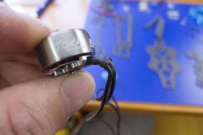
Now remove the outer shrink wrap from the middle of the bend downwards (most motor wires wont fit into the arm with two layers shrink wrap). Make sure not to damage the 3 inner shrink wraps!
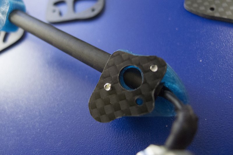
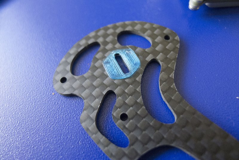
Prepare the motor-mount:
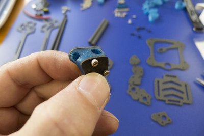
Put two 12mm M2 screws through the lower (smaller) pressure-plate and screw (or push) them loosly all the way into the TPU. Add the top pressure-plate (on top).
Slide the motor wires through the motor mount and the arm:
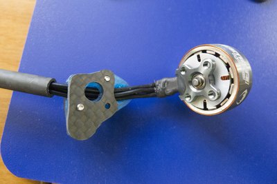
Make sure the wires don't cross each other and the central wire enters the tube on the low side as in the picture (will be outside once the motor is screwed on).
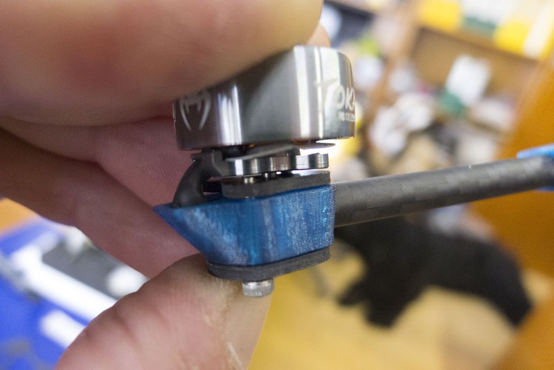
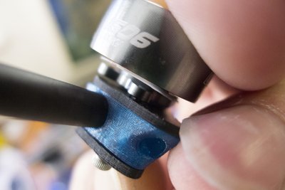
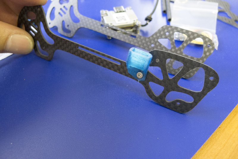
Put an arm-holder on the other side of the tube and push (twisting along the axis helps) the arm into the motor holder as far as in the picture:
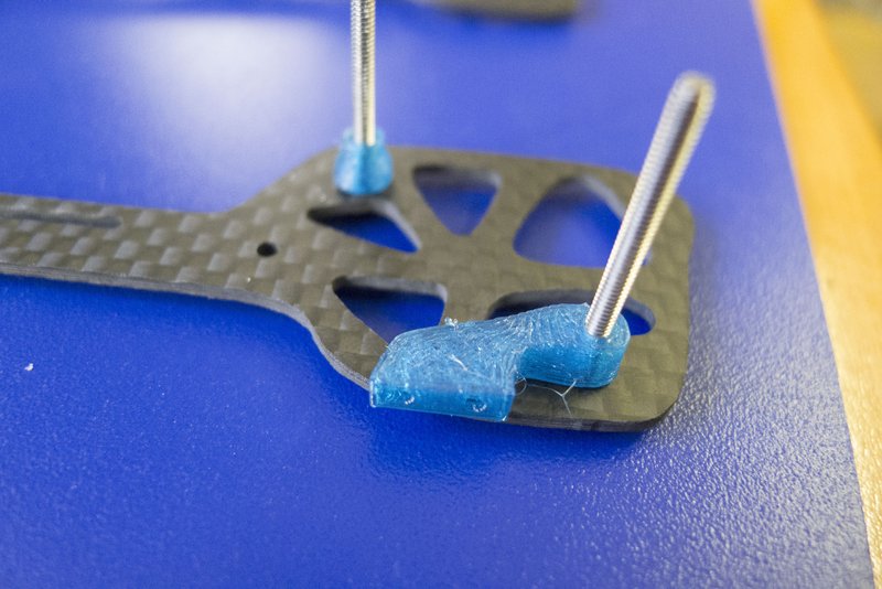
Bend the motor up and pull the cables from the other side to seat them in the TPU:
Now you can screw on the motor. Most of the times it is easier to fasten the screw closer to the cables first, back up the other screw a bit to be able to twist the stator in place and do the other screw last. Make sure to always have at least 2 threads of a screw in the stator (or none at all) when working on the other screw (otherwise you risk ripping out the threading of the stator). If this happens to you: Don't be sad - you can still use that motor on 2 other corners. If that happens to you twice: I told you so!
If both screws are in you can tighten them a bit to make sure they are properly seated.
You will tighten those once you have inserted the side-brace.
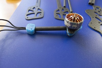
One done - three more to go!
All motors done - go have a break!
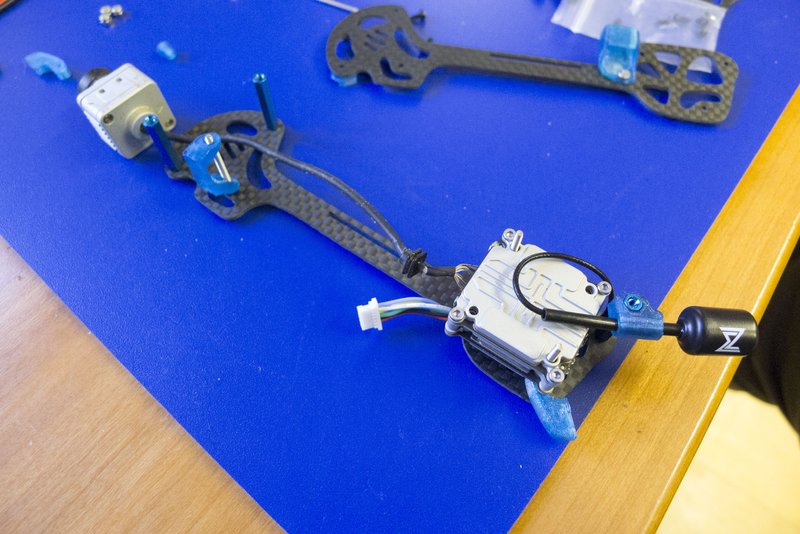
3) Clean section
The "clean section" will carry the Vista (+ camera) and the Battery. It's purpose is to add another level of mechanical decoupling between the motors and the camera. If you are a LOS-guy: You can fly without it ;-)
If you use a micro sized (19mm) cam, insert the spacers. This is not needed when you are using the original DJI camera (20mm). Those determine wich side of the plate is inside (in this build I use the DJI-cam so I took that one out after making the picture).
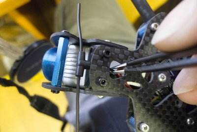
Mount the XT30 holder on the outside of the left sideplate with a 5-6mm M2 screw and a locknut:
Set the bed for the Vista: use two 25mm M2 screws, one spacer and one rear-mount to setup the sideplate. Make sure the rear-mount faces forward from the screw and the flat side faces the plate:
-- extra: JH1.0 connector for the Vista if your FC doesn't feature an DJI connector and dont want your clean section dangling on the vista-cable during maintenance you could solder a plug into the line:
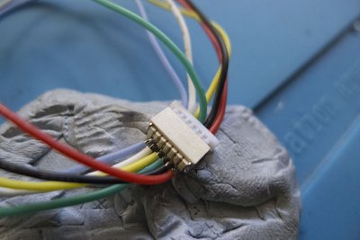
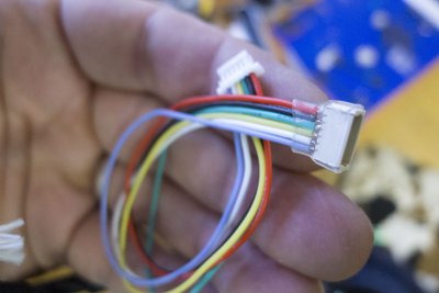
Solder the cable to your Vista:

Make sure to strip as little of the insulation as possible. Especially on the power wire (red) since it's close to the antenna wich is ground.
Antenna mount: the new antennas are handy but they have one downside: the connector is slightly larger than the stem. To get it into the mount you need to pre-stretch the mount. I usually stick some pliers inside, twist it around a bit and do the same thing on the other side:
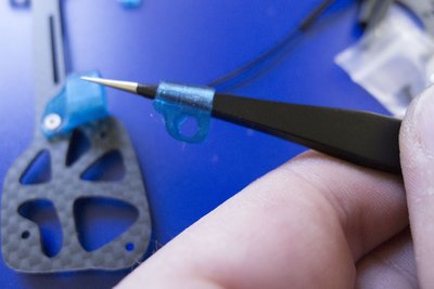
Now you should be able to put the antenna in from the longer side (left on the picture) without damaging the connector. I sometimes need an 1.5 hex driver to push it.
Before we finally put the Vista inside the clean section we still need to add the standoffs and the front mount:
Now add the Vista:
... slide the battery-plate in (Arrows point in direction of flight) and close the section with the oter sideplate.
Use a sharp sciccor to Cut the provided battery matt in two stripes and cut one of the stripes in half and the other in thirds:
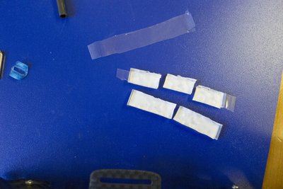
I'm sure you can do better than me but anyway: stick those on top of your battery plate and slide the lipo-strap in:
Run your camera-cable diagonally under your lipo-strap to secure it (we don't want it to hit our FC in flight).
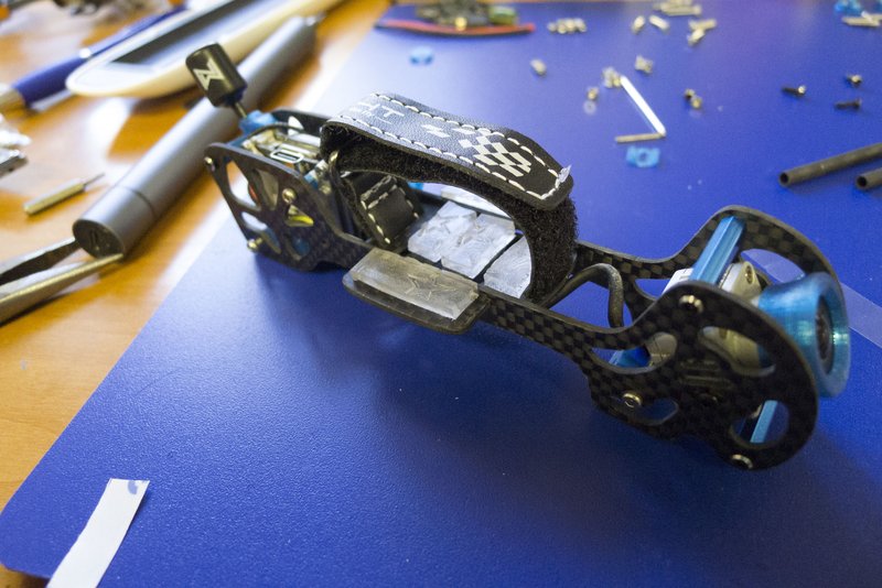
TADA - clean section done!
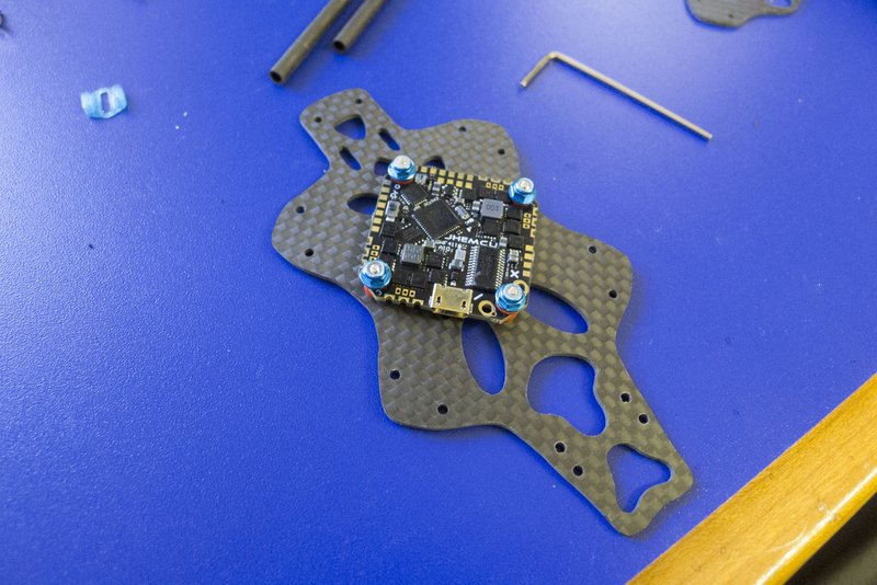
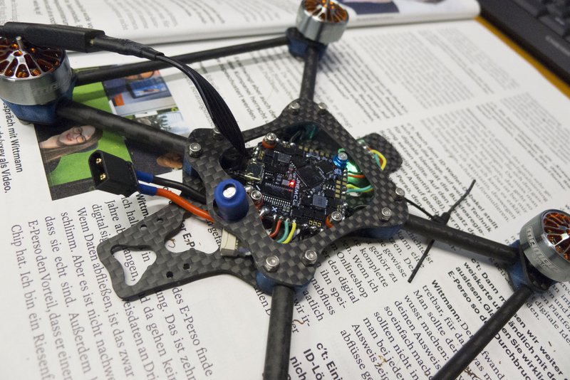
4) Preparing the base plate
Mechanicaly the baseplate is pretty simple but depending on your soldering skills it can still take a while.
Start by screwing on your (conforma coated) AIO:
If your AIO has those extra through-holes for the capacitor solder that one first:
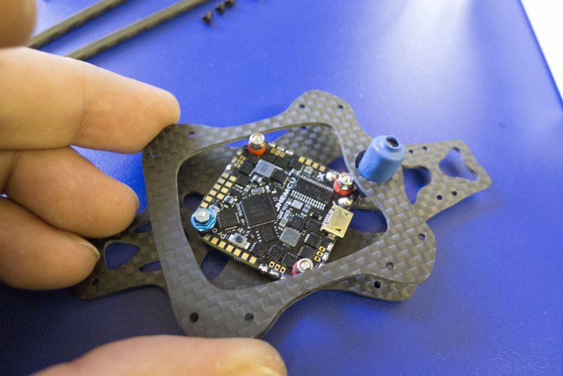
Eyeball the position of the cap by holding the sandwich-plate lined up with the arm-holes. It's easier to pre-bend the legs of the cap before soldering. I recomend to always put some heatshrink on the legs - the big heatshrink around the cap is just for the look ;-)
Solder Power, Vista and RX:
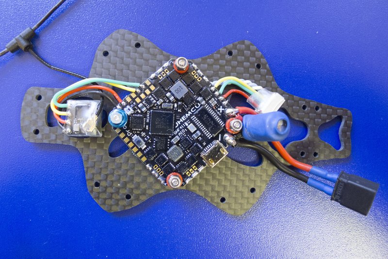
I prefere to position my components before soldering and do each wire one-by-one. It takes a bit longer and stripping the isolation is harder but I usually end up with a much cleaner routing that way.
Make sure you leave a little slack in the power wires to be able to tilt up the clean section a bit for maintenance.
Another importent tip for tight builds: never allow a cable to cross over your gyro - that's a recipe for desaster!
As you can see I leave the SBus and ground wire at a length that can reach the corresponding pads on the AIO in case I ever get a DJI-remote or I sell the build to someone who uses it.
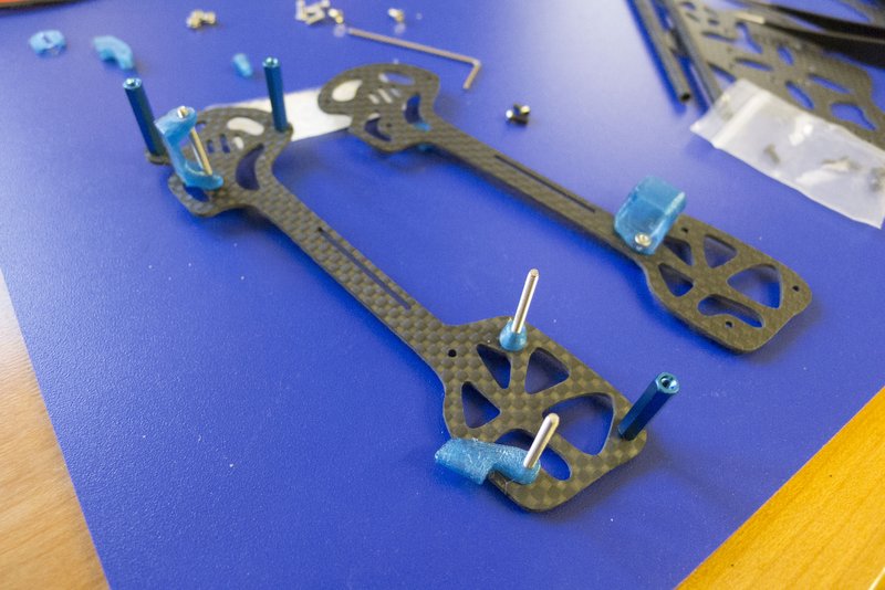
Let's put some arms on:
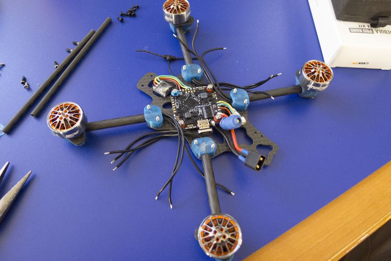
Yeah! It almost looks like it will fly some day. The arm holders are all the same but the holes for the side braces need to point to the center.
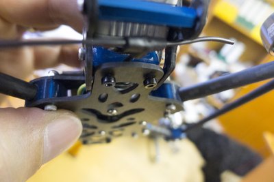
Now solder on your motorwires and put on the sandwich plate:
Be aware that there is a bit of tension in the arm-holders so you need to push the screws together to slide them in most of the time.
Screw the lock nuts on loosly
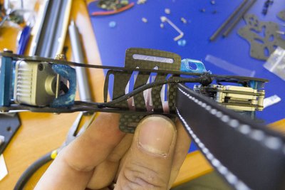
Now insert the side-braces by first twisting one arm a bit (hole for the brace downward):
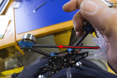
Please use some cardboard or similar between the brace and your palm (I cut myself a couple of times when trying without)
To get the brace into the other motor-mount twist it up again and pull both mounts appart:
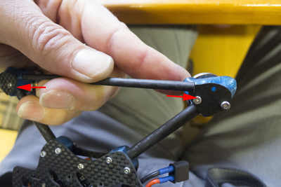
You will need both hands (I had to take the pic somehow).
once it's inside you can seat it by pushing both motor-mounts together with you palms:
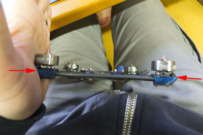
Do the same diagonally to make sure the arms are properly seated on the center side as well. I do this after every hard crash to avoid loosing an arm later on. If this slides in to easy it's time to re-fasten the screws!
Baseplate is done!
Now is a good time for a first smoke test:
(you should do another one once the Vista is connected)
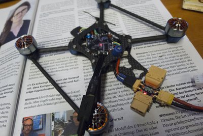
5) The Wedding
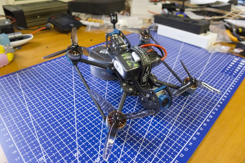
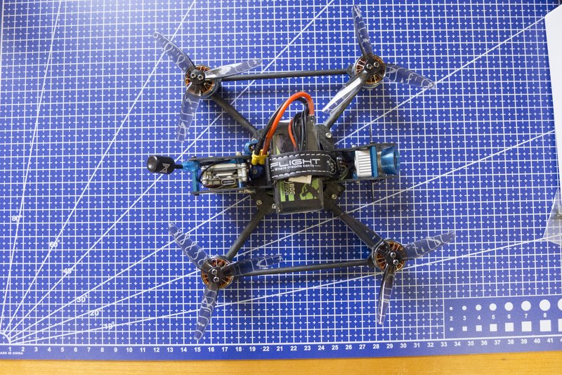
Isn't it beautifull when all the pieces finaly fall into place?
So let's connect the FPV-part (clean section) with the drone-part (base-section)!
Start by connecting the Vista to your AIO (or plug) and slide the XT30 into its mount:
(I had to move the Vista connector a bit further to the outside)
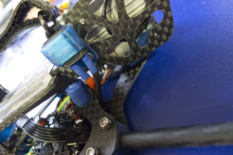
Next fasten the clean-section to the tail with 4 of the self-tapping screws:
Get all screws in loosly until the TPU sits flush on the bottom plate first and fasten them by about 1-1.5 turns until you see the TPU slightly compressing. Try not to rip them out!
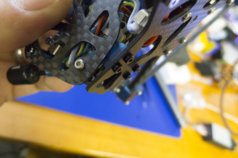
Now put your RX antenna toward the front and insert the remaining two self-tapping screws through the base-plate into the front mount:
There is a little slot for the antenna in the underside of the front mount but I still need pliers to position the antenna correctly while fastening the front screws:
You might not have realized it but you are done - Go have a beer!
... wait: you want to make some neat pictures first (before you crash it):